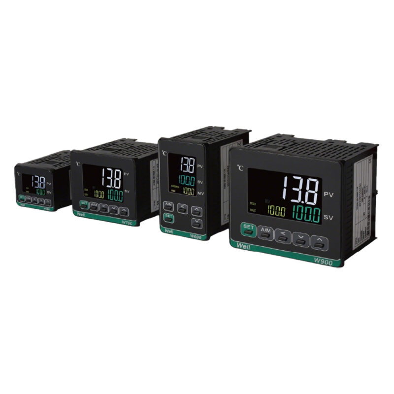
Technicians responsible for equipment commissioning and maintenance have likely encountered these frustrating issues: temperature readings inexplicably drifting or fluctuating wildly, equipment starting and stopping without cause, and compromised temperature control precision. After extensive troubleshooting—ruling out faulty probes and incorrect parameter settings—it often turns out that the vast majority of these malfunctions are caused by electromagnetic interference (EMI). Drawing on practical experience with the W400 temperature controller, I have compiled five actionable methods to address this.
✅ Separate routing for high- and low-voltage lines to eliminate interference at the source.
- Low-voltage signal lines for sensors—such as thermocouples and PT100s—must strictly be kept separate from heating element lines and motor power lines; do not route them through the same conduits or cable trays.
- When routing high-voltage and low-voltage lines in parallel, maintain a minimum separation of 20 cm; where lines must cross, use a 90-degree perpendicular intersection to minimize electromagnetic coupling interference.
- For long sensor cable runs, use specialized shielded compensation cables to reduce signal attenuation and interference.
✅ Single-ended grounding for shielded cables—90% of electricians get it wrong.
Key Rule: Ground at the cabinet end; leave the probe end floating.
The cable shield must be grounded only at the control cabinet's PE grounding busbar; the shield at the temperature probe end must remain floating (ungrounded).
Grounding both ends creates a current loop, which not only fails to provide interference immunity but actually amplifies signal interference; additionally, the shield must strictly never be connected to the neutral wire.
✅ Standardize the grounding layout and distinguish between high-power and low-power ground lines.
- Low-voltage equipment—such as temperature controllers, solid-state relays, and equipment racks—must be connected to a dedicated protective ground line;
- The power ground lines for high-power loads (e.g., motors and contactors) must be grounded independently of the low-voltage instrument ground lines to ensure no mutual interference;
- This arrangement effectively avoids ground potential fluctuations caused by the starting and stopping of high-power equipment, preventing stray currents from entering the temperature measurement circuit and causing data anomalies.
✅ Suppress interference at the source; install anti-interference components.
- Install an RC snubber across the terminals of the AC contactor coil to absorb the high-voltage back-EMF pulse generated upon power-off and eliminate electrical noise;
- Fit anti-interference ferrite rings onto the power lines of temperature control equipment located near the variable frequency drive (VFD); for installations in harsh environments, consider adding a compact power line filter to ensure a clean power supply;
- Position temperature controllers as far away as possible from strong magnetic or heat-generating sources—such as VFD output terminals and transformers—to minimize near-field interference.
✅ Unable to reroute on-site? Emergency fix via parameter fine-tuning.
If on-site wiring cannot be modified, you can access the thermostat's "SET" menu and increase the digital filtering parameter. This automatically filters out transient noise, resolving issues with temperature fluctuations.
⚠️ Important Note: Do not set the filtering parameter too high; excessive filtering causes a lag in temperature measurement response and sluggish control, thereby compromising temperature stability.
💡 Quick Tip: Troubleshooting Temperature Control Interference
- Disconnect the sensor terminals. If the reading stabilizes, the fault stems from on-site wiring or environmental electromagnetic interference.
- If the reading continues to fluctuate erratically after disconnecting the probe, the issue is likely an abnormal power supply to the instrument or a fault within the thermostat unit itself; proceed with targeted repairs.
📝 Summary
Whether dealing with industrial high-temperature equipment, automated variable-frequency assembly lines, or small-scale precision constant-temperature devices, the core logic for resolving interference issues—such as temperature drift or erratic readings—remains the same.
Remember the "Golden Trio" of interference prevention: wiring isolation, single-ended shield grounding, and interference source suppression. Implementing these measures can resolve over 80% of on-site issues—including temperature drift, erratic readings, and accidental equipment start/stop events—ensuring long-term, stable equipment operation.